Beautiful Morning

Glow Plug 6.2 Diagram

Fuse box diagram (fuse layout), emplacemen, and assignment of fuses and relay race Ford Ranger T6 (2011, 2012, 2013, 2014, 2015, 2016, 2017, 2018).

Ford Ranger T6 (2011-2018)

Checking and Replacing Fuses

Fuses and circuit breakers protect your vehicle's electrical system from overloading. If electrical parts in your vehicle are not running, the system may have been overloaded and blown a fuse operating theater tripped a breaker. Before you supercede or repair whatsoever physical phenomenon parts, check the appropriate fuses OR gate breakers.

To check a fuse, look at the silver-colored circle inside the fuse. If the band is halting or melted, replace the conflate.

Notice

  • Ahead replacing fuses check that the key has been removed from the ignition and that all the services are switched sour and/operating theater disengaged.
  • Always unplug the shelling before servicing high current fuses.
  • Always replace a fuse with united that has the mere amperage rating. Victimization a fuse with a high amperage rating can cause serious wire damage and could start a fire.
  • Never replace a off-and-on fuse with anything former than a spick-and-span blend. Use always an intact fuse of the one color.
  • If a fuse blows again contact a qualified service essence.

Position

Location

  • A) Pre-fuse loge.
  • B) Locomotive compartment immix box seat (Power Distribution Corner – PDB)
  • C) Passenger compartment fuse box seat
  • D) Postgraduate current blend box seat (below the PDB)
  • E) The auxiliary fuse box (if equipped)

Type 1

Instrument Panel Fuse Box

The fuse box is located infra and outboard of the steering column behind the access spread over.

Instrument Panel Fuse Box Location

Instrument Panel Fuse Box Diagram (type 1)

A Protected Components
56 20 Fuel pump
57 - Not used
58 - Non used
59 5 Hands-off anti-thievery system (PATS)
60 10 Interior Department lamp, driver's door switch battalion, mood lights, puddle lights, automatic sceneshifter, footwell lamp
61 - Not secondhand
62 5 Rain sensor module
63 5 Tachograph
64 - Not used
65 - Not put-upon
66 20 Driver's door unlock, central double locking
67 5 Plosive speech sound lamp switch
68 - Non misused
69 5 Instrumentate flock, co-ed control module (ICP), trailing and block module
70 20 Central locking
71 5 Air conditioning
72 7.5 Horrify horn
73 5 On-card nosology II
74 20 Main beam
75 15 Front fogginess lamps
76 10 Reversing lamp, rear survey mirror
77 20 Washing machine pump
78 5 Ignition switch
79 15 Radio, Audio signalise DIN, FSAO audio, multi-function display
80 20 Multi-function display, Hi audio, bluetooth audio frequency (2015-2018), brake valve closing (BVC) mental faculty (2011-2014)
81 5 Interior Department motility sensor
82 20 Automatic washer pump ground
83 20 Central locking ground
84 20 Driver's door unlock, central equivocal locking ground
85 7.5 Instrument cluster, parking help module, rearview camera, manual air conditioning, rear view mirror, tracking and blocking faculty
86 10 Restraint system, passenger air-bag deactivation indicator
87 7.5 Tachograph
88 - Not victimised
89 - Not victimized

Railway locomotive Compartment Priming Box

The power distribution box is located in the engine compartment.

Engine Compartment Fuse Box Diagram (type 1)

A Protected Components
1 60 Passenger compartment fuse box supply (Battery)
2 60 Passenger compartment blend loge supply (Battery)
3 50 Petrol: Engine cooling lover
60 Diesel engine: Glow plug control module
4 40 Anti-lock the brakes mental faculty
5 30 Power windows (front man and buttocks)
6 25 2011-2014: Four wheel drive (4WD) motor ground
7 - Non victimised
8 - Not used
9 20 Power seats
10 20 2015-2018: Auxiliary power socket tool panel, soothe top
25 2011-2014: Electrical Windows (presence)
11 30 Blower motor
12 25 Four wheel drive (4WD) motor might
13 20 Dispatcher solenoid
14 20 Heated rear window
15 10 Petrol: Flex-fuel heart
20 Diesel (2013-2016): Vaporizer glow plug
15 Diesel (2011-2012 and 2017-2018): Vaporiser luminescence plug
16 10 Air conditioning clutch
17 25 Power windows (front)
18 25 Windscreen wiper motor
19 25 2011-2014: Wiper motor ground
20 20 Cigar ignitor
21 15 Horn
22 15 2011-2016: Fuel injectors, flex-fuel valve
10 2017-2018: Fire injectors, flex-fuel valve.
23 10 Differential coefficient lock solenoid
24 20 2011-2014: Auxillary power socket (front console)
25 15 Kindling coils, temperature and mass air flow sensor, glow plug module, emptiness control valve (VCV), electronic vacuum governor valve (EVRV)
26 7.5 Electronic control module (ECM)
27 10 Transmission check faculty (TCM)
28 10 Heated exhaust gas oxygen, universal heated exhaust flatulence atomic number 8-sensor, electrical relay coils
29 15 Electronic see to it module (ECM)
30 5 2015-2018: Battery monitoring sensor
15 2011-2014: Battery monitoring sensing element
31 20 Appurtenant power socket (bottom console)
32 5 Air conditioner blackjack switch
33 10 Transmission control module (TCM)
34 5 2014-2018: Bunch head module
2011-2013: PTC heater (where fitted)
35 20 Rider compartment fuse box supply (Kindling)
36 5 Opposing-lock the brakes module
37 10 Headlamp equalisation
38 20 2011-2014: Het seat
39 10 Power mirrors
40 10 Vapourizer pump
41 10 Heated up mirrors
42 10 Alarm horn
43 30 2011-2014: Heated up windscreen (right-handed)
44 30 2011-2014: Hot windscreen (left-wing)
45 25 Anti-lock brake system mental faculty
46 20 2011-2014: Auxillary power socket (bedliner (floor console))
20 2015-2018: Assault and battery isolator
47 40 Trailer tow mental faculty
48 - Not used
49 - Not old
50 5 Ignition relay, relay coils
51 20 2011-2018: Trailer Towage (12/13pin Batt feed / Permanent Live)
30 2011-2014: Electric Windows (behind)
Relay
R1 Central interlock
R2 Wiper on or off
R3 Horn
R4 Air conditioner clutch
R5 Differential lock
R6 Wiper Hi operating theater Lo
R7 Engine cooling fan degraded
R8 Engine cooling fan high
R9 Flex-fuel pump, vaporizer glow plug
R10 Heated rear window
R11 2011-2014: Heated windscreen
R12 Not misused
R13 Electronic control module (ECM) power hold
R14 Ignition
R15 4WD motor 2 (clockwise)
R16 4WD motor 1 (counter right-handed)
R17 4WD motor
R18 Security hooter
R19 Starter
R20 Non utilized
R21 Not used
R22 Non put-upon
R23 Non used
R24 Non used
R25 Not used
R26 Blower motor
R27 Power seat

Auxiliary Fuse Box

Auxiliary Fuse Box Location

Auxiliary Fuse Box Diagram

A Protected Components
1 25 Driving Light
2 15 Position lamp
3 10 LED beacon
4 15 Work lights
5 20 Spare
6 20 Power point
7 15 Reversing lamp
8 15 Direction indicators, stop lamp
9 5 Crew chief
10 5 Disable meld (isolator ground)
11 - Not used
12 - Non used
Relay
R1 Puzzle out lights
R2 LED beacon
R3 Spare
R4 Position lamp
R5 Direction indicator (left-handed)
R6 Focus indicator (right)
R7 Stop lamp
R8 Not used
R9 Not used

Type 2

Control panel Fuse Box

The fuse boxwood is located below and outboard motorboat of the guidance column stern the access cover.

Instrument Panel Fuse Box Location

Instrument Panel Fuse Box Diagram (type 2)

A Protected Components
1 10 Glove box lamp, Map lamp, Battery saver, Operating expense console, Sun visor, Grab handle, Automatic transmission gear shifter (diesel motor)
2 7.5 Not used
3 20 Driver door door latch / Fuel flap unlock relay, Door Doubly / Aux lock electrical relay
4 5 Not utilized
5 20 Not victimized
6 10 Not used
7 10 Non used
8 10 Security horn
9 10 Not used
10 5 Not used
11 5 Interior motion sensor
12 7.5 Electronic panel, Climate control
13 7.5 Instrument clump, Data link connector, Steering column ascendence module
14 10 Not ill-used
15 10 Gateway mental faculty/smart information link connector, OBDII (RHD)
16 15 Child ignition lock
17 5 Battery hardcover sounder, Tracking and Blocking Module
18 5 Ignition switch
19 7.5 Not used
20 7.5 Headlamp master module
21 5 Humidity and in elevator car temperature detector
22 5 Not ill-used
23 10 Inverter, Number one wood door window, Halfway locking system
24 20 Exchange locking system
25 30 Driver door control module (power window - one touch awake/down all doors)
Driver room access king window switching memory (with one retouch/down driver only)
26 30 Passenger threshold dominance module (power window) (unrivaled touch up/down)
27 30 Not used
28 20 Not used
29 30 Left rear door control mental faculty (power window) (one touch up/down)
30 30 Right rear door control module (mogul windowpane) (one hint up/down)
31 15 Tachograph
32 10 Radio receiver transceiver module, SYNC faculty, GPS, Multi-function display, Door entry remote
33 20 Sound unit
34 30 Starter electrical relay
35 5 Restraints control module
36 15 Auto-dimming interior mirror
37 15 Non used
38 30 Power windows (without door control module) (one retouch/down - device driver only)

Engine Compartment Fuse Boxful

Engine Compartment Fuse Box Location (type 2)

Engine Compartment Fuse Box Diagram (type 2)

A Snug Components
1 25 Smart wiper faculty
3 15 Rain sensor
5 20 Auxiliary tycoo point (Rear of centre console)
7 20 Powertrain ensure mental faculty
8 20 Variable intake manifold, Powertrain control module, Evaporative emission canister barf valve, Het oxygen sensing element, Catalyst monitoring sensor (CMS)
10 20 Accessory power point (Cigar lighter)
11 15 Powertrain control mental faculty, Ignition coil
12 15 2.2 L and 3.2 L Duratorq: Winnow private road, Powertrain control module, Glow plugs
13 15 2.5 L Duratec: Heater, Fuel injectors
14 15 2.2 L Duratorq: Powertrain contain faculty, PCV Heater
16 20 Auxiliary king compass point (Cigar barge 2)
17 20 Secondary tycoo point (Buns payload area)
18 10 2.5 L Duratec: Powertrain dominance module, Keep alive power
19 10 Natural philosophy power assist steering
20 10 Lighting control, Headlamp leveling
21 - Not used
22 10 A/C hold
23 15 Head-up presentation, Rear parking aid camera, Adaptive sail control
24 5 Air Conditioning imperativeness switch (Hand-operated transmission vehicles only)
25 10 Anti-shut up brake system
26 10 Mirror set switch, Tachograph
27 5 Accessory Heater
28 10 Powertrain control faculty
29 - Not in use
30 - Not used
31 - Non used
34 15 Stop lamp (Center of attention high riding horse)
35 15 2.2 L Duratorq and 3.2 L Duratorq: Transmission control faculty
36 - Not used
37 10 Heated exterior mirror
43 - Not old
44 - Not used
45 10 2.5 L Duratec: Fuel injectors
46 10 Not used
47 10 Bracken pedal switch
48 20 Horn
49 - Non used
50 - Non utilised
51 - Not used
52 - Not used
53 10 Rear differential lock
54 - Not used
55 - Not in use
Relay
2 Starter motor solenoid relay
4 Blower motor relay
6 2.5 L Duratec: Cooling buff relay (High-speed cooling devotee)
9 Powertrain control module relay
15 Starter relay
32 2.5 L Duratec and 2.2 L Duratorq: Fuel pump relay
33 A/C cling to relay
38 2.5 L Duratec: Chilling fan relay (Low accelerate)
39 Four wheel drive power relay
40 Stop lamp relay (Center in flood mount)
41 Horn relay
42 Four wheel drive motor № 2 relay
86 Four roll drive motor № 1 electrical relay

There are fuses set on the bottom of the fuse box.

To access the bottom of the inning of the fuse box, practice the pursuing:

  1. Release the ii latches, located on some sides of the fuse box seat.
  2. Raise the inboard side of the fuse box from the cradle.
  3. Relocation the commingle box toward the center of the engine compartment.
  4. Pivot the outboard side of the immix box to access the bottom side of meat.
  5. Release the two latches to open the fuse cover.

Engine Compartment Fuse Box Diagram (type 2, bottom)

A Protected Components
56 - Not used
57 - Not used
58 - Not old
59 25 Four Steering wheel Beat back
60 30 Fuel Heart Control Module
61 30 Windscreen Defrost (socialist)
62 50 Body control module 1 (lighting)
63 30 2.5 L Duratec: Low-speed cooling devotee
64 20 Trailer tow connector
65 20 Heated front seating
66 30 Windscreen De-ice (suited)
67 50 Organic structure control faculty 2
68 20 Keister window defroster
69 30 Opposing-lock brake system (Valves)
70 - Not used
71 50 2.5 L Duratec: High-velocity cooling winnow
72 - Non used
73 - Non used
74 20 Driver power derriere
75 - Not used
76 - Not used
77 - Not used
78 - Not used
79 40 Electric fan causative
80 - Not used
81 40 Inverter
82 60 Opposing-lock brake organisation (Pump)
83 25 Windshield wiper centrifugal
84 30 Starter motor solenoid
85 - Not used
87 40 Pok module

High Current Fuse Box

High Current Fuse Box Location

A Protected Components
1 70 2.5 L Duratec: Warmer Control Unit (cold start)
60 2.2 L Duratorq and 3.2 L Duratorq: Beam plug faculty.
2 125 Body control mental faculty 1
3 50 2.5 L Duratec: Body control module 2
2.2 L Duratorq and 3.2 L Duratorq: Trunk see to it mental faculty, Can parking aid camera, Potential dro quality module, Reconciling sail control, Head teacher-up display
4 - Bus through to power distribution box
5 100 Auxiliary heater (if equipped)

Pre-safety fuse box (Battery Mounted Priming Link)

Battery Mounted Fuse Link

A Protected Components
1 225 Body keep in line module 1
2 125 Lepton top executive assist steerage.

This website uses cookies to ameliorate your experience. We'll assume you'ray ok with this, but you can opt-out if you wishing. Cookie settingsACCEPT

Source: https://fusecheck.com/ford/ford-ranger-t6-2011-2018-fuse-diagram

Posted by: irfan0015.blogspot.com

230 Volt Plug Wiring Diagram Ins

CCO/777546/Pixabay

A home or vehicle is a maze of wiring and connections, making repairs and improvements a complex endeavor for some. Learning to read and habit wiring diagrams makes any of these repairs safer endeavors. These simple ocular representations allow you to translate the inside workings of your auto or home and give you the tycoo to execute DIY projects with ease.

What is a Wiring Diagram?

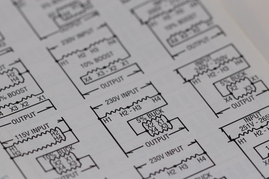
A wiring diagram visually represents the layout of an electrical system or circuit. It focuses on both the layout and the nature of connections between individual wires, as well as where fixtures and components primed into the layout.

Many World Health Organization are raw to the concepts conflate wiring diagrams with formal diagrams. These diagrams actually office in different slipway and have different features. As discussed, a wiring diagram represents the layout of components as they appear on the genuine machine OR gate. A formal offers the same information in the abstract, allowing for easy inclusion of how the parts connect sort o than where they exist right away. A shorter telegraph, for example, may look at the same distance every bit a thirster telegraph in a formal for the sake of space saving and easy visual representation.

Learning the Symbols in Wiring Diagrams

Wiring diagrams usance kidney-shaped graphic symbols to represent different components and connections in an electronic system or circuit. Erudition to recognize these is a key part of using a wiring diagram. The most common symbol is the vertical line, which identifies a wire in the system. A Afro-American Elvis indicates a connection between ii wires. An arch where two wires cross indicates a line hop. While encyclopedism each of these symbols makes indication a wiring diagram easier, many another wiring diagrams offered by manufacturers come with keys that identify components in a plot. These wiring diagrams can also go with detailed labeling for far clarification.

How to Use a Wiring Plot

Wiring diagrams serve common roles in auto repair and home repair. In the home repair setting, you can use a wiring plot to identify the location of wiring, fixtures, and components in a location, and then that you DO not make any repairs that lawsuit damage to a system. Wiring diagrams in the home setting besides facilitate you avoid violating building codes. Wiring diagrams in auto repair serve a similar function, allowing you to execute repairs with efficiency without causing damage to a fomite's systems.

Wiring Diagrams in the Location

Two of the near common applications of the wiring diagram in the home necessitate the installation of receptacles, switches, and light fixtures. You can use up a wiring diagram as reference work when executing any of these DIY improvements in a home. The wiring diagram shows you where wire connections should happen, every bit well as how to connect reason wires for prophylactic connection. Death penalty any electrical installation or repair in a home without a wiring diagram can be dangerous or cause scathe to a abode.

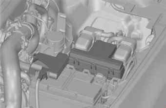
Wiring Diagrams in Auto Repair

Wiring diagrams swear out a similar function in motorcar animate, egg laying out every last the circuitry to facilitate repair and installation. If a car component is non working properly, you can use a wiring diagram to dial in on the wiring and test connections. Those with advance auto recreate skills can also use a wiring diagram to modify a car with aftermarket parts.

Wiring diagrams are fascinating and steadying in a identification number of DIY settings. Before undertaking your next home or auto repair, you can leverage your new ability to show wiring diagrams to ensure a safe and productive experience.

Source: https://www.questionsanswered.net/article/how-to-use-a-wiring-diagram?utm_content=params%3Ao%3D740012%26ad%3DdirN%26qo%3DserpIndex

Posted by: irfan0015.blogspot.com

2001 Vw Jetta 2.0 Serpentine Belt Diagram

How to Replace a Front Wheel Bearing on a VW Jetta

by Marissa RobertUpdated November 07, 2017

Items you will need

  • Tire iron

  • Adjustable wrench

  • Jack

  • 2 jack stands

  • Wire coat hanger

  • Vise

  • Press tool

  • Bearing press

  • Wire brush

  • Arbor press

  • Torque wrench

If you hear squealing from your front wheels, there are a few different problems that might cause it. The brakes are usually the first things that get addressed; but when that squealing persists, often the wheel bearings are to blame. The wheel bearings allow the wheels on your car to spin without too much friction and keep the rest of your wheel hub in good condition. The Volkswagen Jetta has sealed front wheel bearings. Although you cannot adjust them, you can replace them using the right tools.

Pop the hood, and disconnect the negative battery terminal.

Remove the hubcap from your front wheel, and use a tire iron to loosen the bolts holding the wheel on. Remove the axle nut at the center of the wheel with an adjustable wrench. Place a jack under the frame of the Jetta on the front end, and raise the car. Slide jack stands underneath the frame, and lower the front end of the car onto the jack stands.

Pull the front wheel off the Jetta. Unbolt the brake caliper, which grips the wheel hub, from the front wheel, and immediately hang it from a wire coat hanger hooked to the suspension or the frame of the car. Do not let the caliper hang from the brake lines, or you risk damaging them.

Remove the bolts attaching the steering knuckle to the wheel hub. The steering knuckle is a separate part from the axle. It connects the back of the wheel hub to the steering column so that the wheels turn when the steering wheel turns. The steering knuckle is also attached to the front strut assembly, which is a smaller tube running through a large spring. Do not disconnect them from each other. Clamp the bolt assembly connecting the steering knuckle to the strut in a vise.

Install a press tool into the wheel hub, and press the wheel hub out of the front wheel bearing. If the inner bearing sticks inside the wheel hub, clamp the wheel hub in a vise and use a bearing press to pull the inner bearing out. Pull out the old snap ring, and use the press tool to remove the bearing from the knuckle.

Use a wire brush to clean inside the area where the bearing was. Make sure there are no permanent stains or warped areas from the heat. Press the new bearing into the wheel hub with an arbor press. Slide in the new snap ring, and use the old wheel bearing to press the new assembly into the bearing housing on the steering knuckle.

Bolt the steering knuckle onto the wheel hub in the same orientation it was before you removed it. Torque it according to the foot-pound specifications for your model year Jetta.

Place the brake calipers on the wheel hub, and tighten them with a torque wrench according to the recommended foot-pound specifications. Attach the axle nut to the center of the wheel hub, connecting it to the axle, and torque it accordingly too. Put the wheel back on the bolts, and use the torque wrench to tighten the nuts holding it on.

Pop your hubcap back on, and raise the Jetta off the jack stands and lower it back to the ground. Reconnect the negative battery terminal. Always have the front end aligned by a professional after working on the front suspension of your car.

Tips

Different model years with different tires or mild adjustments to the suspension parts have different torque requirements. AutoZone and the Haynes repair manuals are valuable tools. Check them for that information, or ask a professional before you begin your repair.

Warnings

If you are not sure if some of the parts of the bearing housing are fit to use after you clean out that area, ask a professional. If heat has damaged any part of the housing, the new front wheel bearings could fail quickly.

Source: https://itstillruns.com/how-to-replace-a-front-wheel-bearing-on-a-vw-jetta-12253285.html

Posted by: irfan0015.blogspot.com

Vw Jetta Mk3 1998 Relay Diagram

When we last left off with our Volkswagen Jetta Smyth Performance Ute project, I had upgraded the headlights and temporarily finished the exterior with black primer to at least make it all one color. That was three months ago. What has happened with the Jetta since?

The next step I had planned was a cheap suspension lift to make room for the all-terrain tires I plan to install on my second set of wheels. Then the exhaust broke in half. That suddenly took priority, since I can't drive around dragging a pipe on the ground.

My friend Jonah at FIX recently became a Borla distributor and offered to whip together a replacement exhaust for me, something that would sound sporty without being too loud. I had no plans to upgrade the exhaust, but since it needed to get replaced anyway, it was a convenient excuse to "maintainify" it. In other words, modify and improve it during routine maintenance, rather than just replace it with another stock part. I also asked him to help me diagnose the engine misfires, since he had the car in his hands anyway and knows more than I do.

Jonah also offered to take all of my spare Jetta parts off my hands, since he often works on Mark 4 Jettas and can likely put many of them to use. I also needed to make space in the garage to store motorcycles for the winter. So I loaded up the Jetta and our flatbed trailer with everything, including the section we cut off the top rear of the car containing a perfectly good back window. Shortly before Thanksgiving my wife and I drove up there and dropped it all off.

Through no fault of Jonah's, it was all downhill from there. Borla was not responsive to his requests for the parts for my custom exhaust. It took quite some time for him to get them, which pushed the repair into December. Jonah outsources his exhaust work to "a guy," who then also went dark. It took a great deal of poking and prodding by Jonah to make the arrangements for his "guy" to actually take the Jetta and do the work. The Thanksgiving, Christmas, and New Year's holidays certainly didn't help accelerate the timing either.

By now, the car had been sitting so long that the battery, which I just replaced before handing the car over, was dying in between start-ups. No doubt the intense cold snap that gripped New England throughout December didn't help. Also, the old "just hold the car up off the ground" tires had started to leak, requiring them to be pumped up before the car could be driven or moved around the lot. This led to it not getting worked on, which led to another flat tire and flat battery, and so on.

The icing on the cake was when Jonah finally called me during the first week in January. I got excited, thinking the car was ready with a new exhaust and a smooth running engine. Instead, Jonah asked me if I had a spare key for the Jetta. His exhaust guy had locked my key inside. A spare key has been on my to-do list, but the car only came with one, and that key was now locked inside the car it belongs to. So I gave Jonah the car's vehicle identification number, and they had a second key made at their expense. I guess that's one less thing I need to do when I finally get it back.

Finally, Jonah gave me a call to discuss some specific exhaust options as his exhaust guy was about to work on the Jetta, really this time. He actually had a stock Jetta muffler kicking around, used of course, that he offered as a low-cost option, in addition to the 2.25 and 2.5-inch Borla exhausts. I decided that I wanted all-new parts that would last and a little bit of a rumble, so I opted for the 2.25-inch exhaust since I'm not going to be looking for any big horsepower out of this car.

Once the exhaust was installed and he got the car back, he dove into the rest of it. Jonah quickly tracked the rough running problem down to a stuck valve in the vacuum lines. After replacing it, the crummy spark plugs it came with, and a bunch of other minor tweaks he threw in for free (including the second key), the car ran perfectly. It still had a leaky exhaust gasket at the turbo, but he honestly said he didn't have time to work on it now, and I just wanted the car back anyway, so we agreed to skip it for now.

Originally I'd had thoughts of taking the Jetta Ute to the LeMons Rally, but all the delays lingered through the Rally itself, making this impossible. I could've done it if I'd just gone to the muffler shop and had it in and out in one day, but I decided to help my friend out, and, well, you've read what happened. To his credit, Jonah did a bunch of work and diagnosis that he didn't charge me for to help make up for the fact that his muffler guy kind of screwed me on this.

It's not all bad. We've been able to keep the driveway plowed better without the extra car and trailer in the way. December was so cold that I wasn't able to work in my unheated garage anyway. We also parked my wife's Ford Flex inside during December's arctic chill so there wouldn't have been space to work on the Jetta anyway.

I'll finally be getting the Jetta back next week, with a relatively small repair bill considering the time it was at the shop and how much work was done on it. You know the saying: "Good, cheap, or fast—pick any two." It looks like I've picked good and cheap. Then I can finally get back to work. Aside from the exhaust gasket, I plan to start by giving the Jetta a bit of a lift to accommodate the larger tires I've picked out for it.

Posted by: irfan0015.blogspot.com

Source: https://www.thedrive.com/news/17455/a-comedy-of-errors-with-the-vw-jetta-smyth-ute

1998 Winnebago Chieftain Dash Wiring Diagram

Reply

 
Old 06-09-2014, 02:46 PM #1

Winnebago Camper

Join Date: Jun 2014

Posts: 7

New owner 98 Chieftain 33wb. Stereo/electrical help please.


This is my first RV so all this is pretty new to me. Lets start with my first 2 questions.

1st
My chieftain has 4 surround sound speakers mounted but none of them work. I only get tv and stereo sound from a speaker that is mounted under the couch and one that is mounted behind a return vent below the fridge. Any ideas as to what I need to check here? I have no clue as to what/where these are supposed to be wired to. Is there an amp somewhere, or is there supposed to be a home theater receiver to power them or what? I am clueless...

2nd
I have an inverter mounted up front in the passengers side overhead. It doesn't work. What is a suitable replacement? It is currently an Airpax Dimensions ADI-12/140tl and it has a GFI on the front of it. Let me know if you need more info on this.

bigo181979 is offline Reply With Quote
Old 06-09-2014, 03:48 PM #2

Winnie-Wise

BFlinn181's Avatar

Join Date: Jan 2012

Location: Cincinnati

Posts: 486

:welcome:

If the speakers are original, they would be on the Winnebago wiring diagram for your RV. Check at the Winnebago website and you can download wiring, plumbing, owner's manual for your Chieftain. They may be wired through the dash radio for an amplifier, but that's just a guess.

On the Inverter, check that it's connected to 12 v. power source. If it is and still doesn't work, check the GFI. If you want to replace it, Assess what you want to power with it and shop for an inverter with wattage to cover your needs. In an overhead compartment near TV it probably is for TV, DVD, VCR, game power when no shore power around. Be sure your new inverter shuts itself down before running down batteries too much.

TV in view of the driver by law must not be powered when underway. If the inverter was added to power TV on the road, be aware it could be a ticket if caught.

__________________

Bob & Donna
'98 Gulf Stream Sun Voyager DP being pushed by a '00 Beetle TDI

BFlinn181 is offline Reply With Quote
Old 06-09-2014, 04:10 PM #3

Winnebago Camper

Join Date: Jun 2014

Posts: 7

Quote:

Originally Posted by BFlinn181 View Post

:welcome:

If the speakers are original, they would be on the Winnebago wiring diagram for your RV. Check at the Winnebago website and you can download wiring, plumbing, owner's manual for your Chieftain. They may be wired through the dash radio for an amplifier, but that's just a guess.

On the Inverter, check that it's connected to 12 v. power source. If it is and still doesn't work, check the GFI. If you want to replace it, Assess what you want to power with it and shop for an inverter with wattage to cover your needs. In an overhead compartment near TV it probably is for TV, DVD, VCR, game power when no shore power around. Be sure your new inverter shuts itself down before running down batteries too much.

TV in view of the driver by law must not be powered when underway. If the inverter was added to power TV on the road, be aware it could be a ticket if caught.

I do know that it is factory, its part of the premium sound package and is wired into factory plugs. I will check the winnabego sight and see what I can find.
As for the inverter yeah I had it tested and its done, I would be running a TV DVD and possibly a 5.1 surround home stereo system with it. As for the tv location it is mounted far enough back that it would not be in view of the driver.
Thanks for the info.

bigo181979 is offline Reply With Quote
Old 06-09-2014, 04:25 PM #4

Winnebago Owner

homeless's Avatar

Join Date: Mar 2012

Location: Fulltime RVer

Posts: 212

Howdy I got an inexpensive Radio Shack 250 watt inverter to run my TV. But I am sure some of these guys can tell you where to find an inverter that is more expensive.

homeless is offline Reply With Quote
Old 06-09-2014, 04:48 PM #5

Winnebago Owner

Patrol 65's Avatar

Join Date: Oct 2011

Location: Charleston, SC

Posts: 80

Check the back of the speakers to make sure that they are connected. If they are connected, find another small speaker to hook to the wires to see if there is a signal coming through the wires. If not, I would check the connections on the amplifier. Mine is located near the floor under the dash on the passenger side of the dashboard. My inverter also doesn't work. When I tried to turn it on I lost electrical power to the tv. I guess that mine is toast.

__________________
Nathan and Linda, 2000 Winnebago Chieftain 35U, F53 Chassis, Banks Power Pack

Patrol 65 is offline Reply With Quote
Old 06-09-2014, 04:48 PM #6

Winnebago Camper

Join Date: Jun 2014

Posts: 7

Ok so what I found was on page 19 of this diagram it shows there is an amp http://www.winnebagoind.com/diagram/1998/125854.pdf now I just have to figure out where that is. I am guessing its up under on the passenger side of the dash. From what I am reading the 2 speakers I have sound from are what they are calling "subs" they are both 6x9's, not exactly a sub imo, but anyway. I wonder why I am only getting sound from the "subs" then.

bigo181979 is offline Reply With Quote
Old 06-09-2014, 04:54 PM #7

Winnebago Camper

Join Date: Jun 2014

Posts: 7

My other thought is that someone has probably put a different head unit in it. It has a blaupunkt unit, so there is the possibility that the wired it incorrectly too... I guess I have some diag work to do...

bigo181979 is offline Reply With Quote
Old 06-09-2014, 05:15 PM #8

Winnebago Camper

Join Date: Jun 2014

Posts: 7

Oh and not that it matters but its a 1998 chieftain 34wy not a 33

bigo181979 is offline Reply With Quote
Old 06-09-2014, 05:27 PM #9

Winnebago Owner

ladagobago's Avatar

Join Date: Dec 2010

Location: DW Driver -Winter Englewood FL, Summer Willingboro NJ

Posts: 116

sub woofer


the subwoofer is driven off the radio speaker outputs.
the wiring diagram is found on drawing 130344 kl36l pusher chassis wiring.

the speakers in the corners were driven of a stereo amp found on the passenger side under the dash. inputs and outputs were wired accross the dash and connect to jones plugs behind the radio.

I ripped out all that garbage and install my own stereo "real surround" with powered subwoofer. had to rip out the tilt drawer and cut open the fire wall. then made my own aluminum box to make a home for the new stereo reciever complete with HDMI and optic cable to the top where we put in a new LED TV. The inverter works great. powered by either the battery or shore power.

most of all those speaker wire are purple and run through the cabinets. The winnebago subwoofers were a real joke. I left them there.

__________________
La Dagobago
99 36 FL Winne Chieftain 5.9 ISB Turbo Cummins DP, 24' box with 1972 V12 XKE Jag and HD Sporty Hobby of 1970's Suzuki dirt bike restoration. Visit my blog.

ladagobago is offline Reply With Quote
Old 06-09-2014, 05:52 PM #10

Winnebago Camper

Join Date: Jun 2014

Posts: 7

Quote:

Originally Posted by ladagobago View Post

the subwoofer is driven off the radio speaker outputs.
the wiring diagram is found on drawing 130344 kl36l pusher chassis wiring.

the speakers in the corners were driven of a stereo amp found on the passenger side under the dash. inputs and outputs were wired accross the dash and connect to jones plugs behind the radio.

I ripped out all that garbage and install my own stereo "real surround" with powered subwoofer. had to rip out the tilt drawer and cut open the fire wall. then made my own aluminum box to make a home for the new stereo reciever complete with HDMI and optic cable to the top where we put in a new LED TV. The inverter works great. powered by either the battery or shore power.

most of all those speaker wire are purple and run through the cabinets. The winnebago subwoofers were a real joke. I left them there.

Do you have a link to that diagram? I googled it but got no luck. By real surround do you mean like a home theater receiver and sound system? Or did you use a car audio setup with a 5.1 processor? And yeah the 6x9's are laughable!

My thoughts are to put in a surround sound system to run with the tv/bluray and a seperate audio system for just music.

bigo181979 is offline Reply With Quote
Old 06-10-2014, 11:22 AM #11

Winnebago Camper

Join Date: Jun 2014

Posts: 7

Well did some work last night. Got power to the amp but no sound to the speakers, tested all the speakers, they all work. Although they sound like crap lol.

So with a bad amp and crappy speakers it looks like I am going to wire up 2 systems. I will have a dedicated car audio system and a dedicated home theater system when I am done.

bigo181979 is offline Reply With Quote

Reply


Currently Active Users Viewing This Thread: 1 (0 members and 1 guests)

Posting Rules

You may not post new threads

You may not post replies

You may not post attachments

You may not edit your posts


BB code is On

Smilies are On

[IMG] code is On

HTML code is Off

Trackbacks are Off

Pingbacks are Off

Refbacks are Off


Forum Rules


Similar Threads
Thread Thread Starter Forum Replies Last Post
Help, please! 2008 Journey 39z 12V electrical problem Birddogman Winnebago Class A Motorhomes 6 11-13-2013 05:45 PM
1998 Chieftain 33wb F53 Chassis -what to tow? Rkh Towing, Hitching and Vehicles 9 01-15-2012 12:49 PM
Need More Help Please! Electrical Kazoo Tom Electrical | Charging, Solar and Electronics 8 04-18-2006 01:27 PM

  • How Long Do RV Batteries Last?

  • Don't Go RVing Without This Camping Checklist!

  • What Can I Leave In My RV Over The Winter?

  • DIY RV Christmas Decorations That Are Easy To Make

All times are GMT -6. The time now is 11:39 AM.

Source: https://www.winnieowners.com/forums/f260/new-owner-98-chieftain-33wb-stereo-electrical-help-please-207007.html

Posted by: irfan0015.blogspot.com