Fuse box diagram (fuse layout), emplacemen, and assignment of fuses and relay race Ford Ranger T6 (2011, 2012, 2013, 2014, 2015, 2016, 2017, 2018).

Checking and Replacing Fuses
Fuses and circuit breakers protect your vehicle's electrical system from overloading. If electrical parts in your vehicle are not running, the system may have been overloaded and blown a fuse operating theater tripped a breaker. Before you supercede or repair whatsoever physical phenomenon parts, check the appropriate fuses OR gate breakers.
To check a fuse, look at the silver-colored circle inside the fuse. If the band is halting or melted, replace the conflate.
Notice
- Ahead replacing fuses check that the key has been removed from the ignition and that all the services are switched sour and/operating theater disengaged.
- Always unplug the shelling before servicing high current fuses.
- Always replace a fuse with united that has the mere amperage rating. Victimization a fuse with a high amperage rating can cause serious wire damage and could start a fire.
- Never replace a off-and-on fuse with anything former than a spick-and-span blend. Use always an intact fuse of the one color.
- If a fuse blows again contact a qualified service essence.
Position
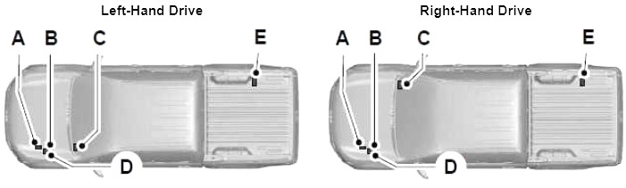
- A) Pre-fuse loge.
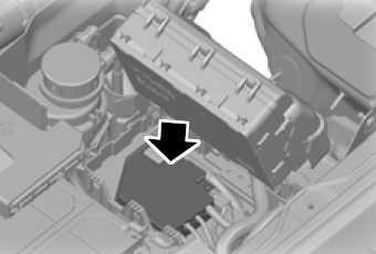
- B) Locomotive compartment immix box seat (Power Distribution Corner – PDB)
- C) Passenger compartment fuse box seat
- D) Postgraduate current blend box seat (below the PDB)
- E) The auxiliary fuse box (if equipped)
Type 1
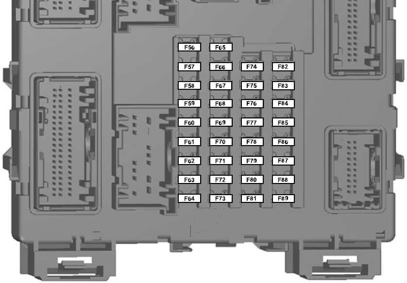
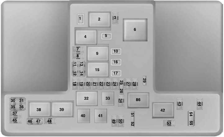
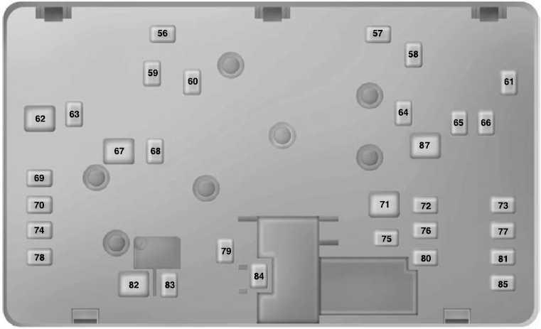
Instrument Panel Fuse Box
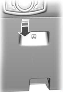
The fuse box is located infra and outboard of the steering column behind the access spread over.
| № | A | Protected Components |
|---|---|---|
| 56 | 20 | Fuel pump |
| 57 | - | Not used |
| 58 | - | Non used |
| 59 | 5 | Hands-off anti-thievery system (PATS) |
| 60 | 10 | Interior Department lamp, driver's door switch battalion, mood lights, puddle lights, automatic sceneshifter, footwell lamp |
| 61 | - | Not secondhand |
| 62 | 5 | Rain sensor module |
| 63 | 5 | Tachograph |
| 64 | - | Not used |
| 65 | - | Not put-upon |
| 66 | 20 | Driver's door unlock, central double locking |
| 67 | 5 | Plosive speech sound lamp switch |
| 68 | - | Non misused |
| 69 | 5 | Instrumentate flock, co-ed control module (ICP), trailing and block module |
| 70 | 20 | Central locking |
| 71 | 5 | Air conditioning |
| 72 | 7.5 | Horrify horn |
| 73 | 5 | On-card nosology II |
| 74 | 20 | Main beam |
| 75 | 15 | Front fogginess lamps |
| 76 | 10 | Reversing lamp, rear survey mirror |
| 77 | 20 | Washing machine pump |
| 78 | 5 | Ignition switch |
| 79 | 15 | Radio, Audio signalise DIN, FSAO audio, multi-function display |
| 80 | 20 | Multi-function display, Hi audio, bluetooth audio frequency (2015-2018), brake valve closing (BVC) mental faculty (2011-2014) |
| 81 | 5 | Interior Department motility sensor |
| 82 | 20 | Automatic washer pump ground |
| 83 | 20 | Central locking ground |
| 84 | 20 | Driver's door unlock, central equivocal locking ground |
| 85 | 7.5 | Instrument cluster, parking help module, rearview camera, manual air conditioning, rear view mirror, tracking and blocking faculty |
| 86 | 10 | Restraint system, passenger air-bag deactivation indicator |
| 87 | 7.5 | Tachograph |
| 88 | - | Not victimised |
| 89 | - | Not victimized |
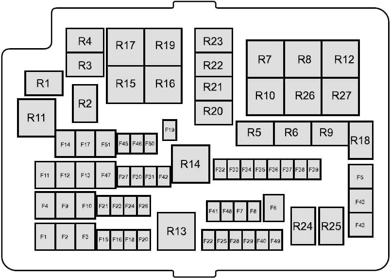
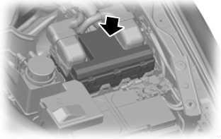
Railway locomotive Compartment Priming Box
The power distribution box is located in the engine compartment.
| № | A | Protected Components |
|---|---|---|
| 1 | 60 | Passenger compartment fuse box supply (Battery) |
| 2 | 60 | Passenger compartment blend loge supply (Battery) |
| 3 | 50 | Petrol: Engine cooling lover |
| 60 | Diesel engine: Glow plug control module | |
| 4 | 40 | Anti-lock the brakes mental faculty |
| 5 | 30 | Power windows (front man and buttocks) |
| 6 | 25 | 2011-2014: Four wheel drive (4WD) motor ground |
| 7 | - | Non victimised |
| 8 | - | Not used |
| 9 | 20 | Power seats |
| 10 | 20 | 2015-2018: Auxiliary power socket tool panel, soothe top |
| 25 | 2011-2014: Electrical Windows (presence) | |
| 11 | 30 | Blower motor |
| 12 | 25 | Four wheel drive (4WD) motor might |
| 13 | 20 | Dispatcher solenoid |
| 14 | 20 | Heated rear window |
| 15 | 10 | Petrol: Flex-fuel heart |
| 20 | Diesel (2013-2016): Vaporizer glow plug | |
| 15 | Diesel (2011-2012 and 2017-2018): Vaporiser luminescence plug | |
| 16 | 10 | Air conditioning clutch |
| 17 | 25 | Power windows (front) |
| 18 | 25 | Windscreen wiper motor |
| 19 | 25 | 2011-2014: Wiper motor ground |
| 20 | 20 | Cigar ignitor |
| 21 | 15 | Horn |
| 22 | 15 | 2011-2016: Fuel injectors, flex-fuel valve |
| 10 | 2017-2018: Fire injectors, flex-fuel valve. | |
| 23 | 10 | Differential coefficient lock solenoid |
| 24 | 20 | 2011-2014: Auxillary power socket (front console) |
| 25 | 15 | Kindling coils, temperature and mass air flow sensor, glow plug module, emptiness control valve (VCV), electronic vacuum governor valve (EVRV) |
| 26 | 7.5 | Electronic control module (ECM) |
| 27 | 10 | Transmission check faculty (TCM) |
| 28 | 10 | Heated exhaust gas oxygen, universal heated exhaust flatulence atomic number 8-sensor, electrical relay coils |
| 29 | 15 | Electronic see to it module (ECM) |
| 30 | 5 | 2015-2018: Battery monitoring sensor |
| 15 | 2011-2014: Battery monitoring sensing element | |
| 31 | 20 | Appurtenant power socket (bottom console) |
| 32 | 5 | Air conditioner blackjack switch |
| 33 | 10 | Transmission control module (TCM) |
| 34 | 5 | 2014-2018: Bunch head module |
| 2011-2013: PTC heater (where fitted) | ||
| 35 | 20 | Rider compartment fuse box supply (Kindling) |
| 36 | 5 | Opposing-lock the brakes module |
| 37 | 10 | Headlamp equalisation |
| 38 | 20 | 2011-2014: Het seat |
| 39 | 10 | Power mirrors |
| 40 | 10 | Vapourizer pump |
| 41 | 10 | Heated up mirrors |
| 42 | 10 | Alarm horn |
| 43 | 30 | 2011-2014: Heated up windscreen (right-handed) |
| 44 | 30 | 2011-2014: Hot windscreen (left-wing) |
| 45 | 25 | Anti-lock brake system mental faculty |
| 46 | 20 | 2011-2014: Auxillary power socket (bedliner (floor console)) |
| 20 | 2015-2018: Assault and battery isolator | |
| 47 | 40 | Trailer tow mental faculty |
| 48 | - | Not used |
| 49 | - | Not old |
| 50 | 5 | Ignition relay, relay coils |
| 51 | 20 | 2011-2018: Trailer Towage (12/13pin Batt feed / Permanent Live) |
| 30 | 2011-2014: Electric Windows (behind) | |
| | ||
| R1 | Central interlock | |
| R2 | Wiper on or off | |
| R3 | Horn | |
| R4 | Air conditioner clutch | |
| R5 | Differential lock | |
| R6 | Wiper Hi operating theater Lo | |
| R7 | Engine cooling fan degraded | |
| R8 | Engine cooling fan high | |
| R9 | Flex-fuel pump, vaporizer glow plug | |
| R10 | Heated rear window | |
| R11 | 2011-2014: Heated windscreen | |
| R12 | Not misused | |
| R13 | Electronic control module (ECM) power hold | |
| R14 | Ignition | |
| R15 | 4WD motor 2 (clockwise) | |
| R16 | 4WD motor 1 (counter right-handed) | |
| R17 | 4WD motor | |
| R18 | Security hooter | |
| R19 | Starter | |
| R20 | Non utilized | |
| R21 | Not used | |
| R22 | Non put-upon | |
| R23 | Non used | |
| R24 | Non used | |
| R25 | Not used | |
| R26 | Blower motor | |
| R27 | Power seat | |
Auxiliary Fuse Box
| № | A | Protected Components |
|---|---|---|
| 1 | 25 | Driving Light |
| 2 | 15 | Position lamp |
| 3 | 10 | LED beacon |
| 4 | 15 | Work lights |
| 5 | 20 | Spare |
| 6 | 20 | Power point |
| 7 | 15 | Reversing lamp |
| 8 | 15 | Direction indicators, stop lamp |
| 9 | 5 | Crew chief |
| 10 | 5 | Disable meld (isolator ground) |
| 11 | - | Not used |
| 12 | - | Non used |
| | ||
| R1 | Puzzle out lights | |
| R2 | LED beacon | |
| R3 | Spare | |
| R4 | Position lamp | |
| R5 | Direction indicator (left-handed) | |
| R6 | Focus indicator (right) | |
| R7 | Stop lamp | |
| R8 | Not used | |
| R9 | Not used | |
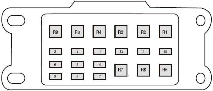
Type 2
Control panel Fuse Box
The fuse boxwood is located below and outboard motorboat of the guidance column stern the access cover.
| № | A | Protected Components |
|---|---|---|
| 1 | 10 | Glove box lamp, Map lamp, Battery saver, Operating expense console, Sun visor, Grab handle, Automatic transmission gear shifter (diesel motor) |
| 2 | 7.5 | Not used |
| 3 | 20 | Driver door door latch / Fuel flap unlock relay, Door Doubly / Aux lock electrical relay |
| 4 | 5 | Not utilized |
| 5 | 20 | Not victimized |
| 6 | 10 | Not used |
| 7 | 10 | Non used |
| 8 | 10 | Security horn |
| 9 | 10 | Not used |
| 10 | 5 | Not used |
| 11 | 5 | Interior motion sensor |
| 12 | 7.5 | Electronic panel, Climate control |
| 13 | 7.5 | Instrument clump, Data link connector, Steering column ascendence module |
| 14 | 10 | Not ill-used |
| 15 | 10 | Gateway mental faculty/smart information link connector, OBDII (RHD) |
| 16 | 15 | Child ignition lock |
| 17 | 5 | Battery hardcover sounder, Tracking and Blocking Module |
| 18 | 5 | Ignition switch |
| 19 | 7.5 | Not used |
| 20 | 7.5 | Headlamp master module |
| 21 | 5 | Humidity and in elevator car temperature detector |
| 22 | 5 | Not ill-used |
| 23 | 10 | Inverter, Number one wood door window, Halfway locking system |
| 24 | 20 | Exchange locking system |
| 25 | 30 | Driver door control module (power window - one touch awake/down all doors) |
| Driver room access king window switching memory (with one retouch/down driver only) | ||
| 26 | 30 | Passenger threshold dominance module (power window) (unrivaled touch up/down) |
| 27 | 30 | Not used |
| 28 | 20 | Not used |
| 29 | 30 | Left rear door control mental faculty (power window) (one touch up/down) |
| 30 | 30 | Right rear door control module (mogul windowpane) (one hint up/down) |
| 31 | 15 | Tachograph |
| 32 | 10 | Radio receiver transceiver module, SYNC faculty, GPS, Multi-function display, Door entry remote |
| 33 | 20 | Sound unit |
| 34 | 30 | Starter electrical relay |
| 35 | 5 | Restraints control module |
| 36 | 15 | Auto-dimming interior mirror |
| 37 | 15 | Non used |
| 38 | 30 | Power windows (without door control module) (one retouch/down - device driver only) |
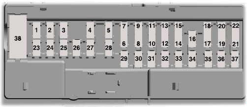
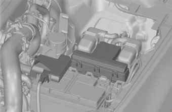
Engine Compartment Fuse Boxful
| № | A | Snug Components |
|---|---|---|
| 1 | 25 | Smart wiper faculty |
| 3 | 15 | Rain sensor |
| 5 | 20 | Auxiliary tycoo point (Rear of centre console) |
| 7 | 20 | Powertrain ensure mental faculty |
| 8 | 20 | Variable intake manifold, Powertrain control module, Evaporative emission canister barf valve, Het oxygen sensing element, Catalyst monitoring sensor (CMS) |
| 10 | 20 | Accessory power point (Cigar lighter) |
| 11 | 15 | Powertrain control mental faculty, Ignition coil |
| 12 | 15 | 2.2 L and 3.2 L Duratorq: Winnow private road, Powertrain control module, Glow plugs |
| 13 | 15 | 2.5 L Duratec: Heater, Fuel injectors |
| 14 | 15 | 2.2 L Duratorq: Powertrain contain faculty, PCV Heater |
| 16 | 20 | Auxiliary king compass point (Cigar barge 2) |
| 17 | 20 | Secondary tycoo point (Buns payload area) |
| 18 | 10 | 2.5 L Duratec: Powertrain dominance module, Keep alive power |
| 19 | 10 | Natural philosophy power assist steering |
| 20 | 10 | Lighting control, Headlamp leveling |
| 21 | - | Not used |
| 22 | 10 | A/C hold |
| 23 | 15 | Head-up presentation, Rear parking aid camera, Adaptive sail control |
| 24 | 5 | Air Conditioning imperativeness switch (Hand-operated transmission vehicles only) |
| 25 | 10 | Anti-shut up brake system |
| 26 | 10 | Mirror set switch, Tachograph |
| 27 | 5 | Accessory Heater |
| 28 | 10 | Powertrain control faculty |
| 29 | - | Not in use |
| 30 | - | Not used |
| 31 | - | Non used |
| 34 | 15 | Stop lamp (Center of attention high riding horse) |
| 35 | 15 | 2.2 L Duratorq and 3.2 L Duratorq: Transmission control faculty |
| 36 | - | Not used |
| 37 | 10 | Heated exterior mirror |
| 43 | - | Not old |
| 44 | - | Not used |
| 45 | 10 | 2.5 L Duratec: Fuel injectors |
| 46 | 10 | Not used |
| 47 | 10 | Bracken pedal switch |
| 48 | 20 | Horn |
| 49 | - | Non used |
| 50 | - | Non utilised |
| 51 | - | Not used |
| 52 | - | Not used |
| 53 | 10 | Rear differential lock |
| 54 | - | Not used |
| 55 | - | Not in use |
| | ||
| 2 | Starter motor solenoid relay | |
| 4 | Blower motor relay | |
| 6 | 2.5 L Duratec: Cooling buff relay (High-speed cooling devotee) | |
| 9 | Powertrain control module relay | |
| 15 | Starter relay | |
| 32 | 2.5 L Duratec and 2.2 L Duratorq: Fuel pump relay | |
| 33 | A/C cling to relay | |
| 38 | 2.5 L Duratec: Chilling fan relay (Low accelerate) | |
| 39 | Four wheel drive power relay | |
| 40 | Stop lamp relay (Center in flood mount) | |
| 41 | Horn relay | |
| 42 | Four wheel drive motor № 2 relay | |
| 86 | Four roll drive motor № 1 electrical relay | |
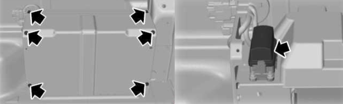
There are fuses set on the bottom of the fuse box.
To access the bottom of the inning of the fuse box, practice the pursuing:
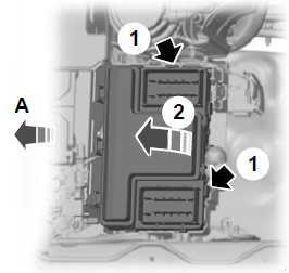
- Release the ii latches, located on some sides of the fuse box seat.
- Raise the inboard side of the fuse box from the cradle.
- Relocation the commingle box toward the center of the engine compartment.
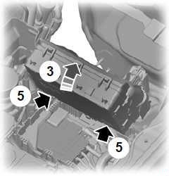
- Pivot the outboard side of the immix box to access the bottom side of meat.
- Release the two latches to open the fuse cover.
| № | A | Protected Components |
|---|---|---|
| 56 | - | Not used |
| 57 | - | Not used |
| 58 | - | Not old |
| 59 | 25 | Four Steering wheel Beat back |
| 60 | 30 | Fuel Heart Control Module |
| 61 | 30 | Windscreen Defrost (socialist) |
| 62 | 50 | Body control module 1 (lighting) |
| 63 | 30 | 2.5 L Duratec: Low-speed cooling devotee |
| 64 | 20 | Trailer tow connector |
| 65 | 20 | Heated front seating |
| 66 | 30 | Windscreen De-ice (suited) |
| 67 | 50 | Organic structure control faculty 2 |
| 68 | 20 | Keister window defroster |
| 69 | 30 | Opposing-lock brake system (Valves) |
| 70 | - | Not used |
| 71 | 50 | 2.5 L Duratec: High-velocity cooling winnow |
| 72 | - | Non used |
| 73 | - | Non used |
| 74 | 20 | Driver power derriere |
| 75 | - | Not used |
| 76 | - | Not used |
| 77 | - | Not used |
| 78 | - | Not used |
| 79 | 40 | Electric fan causative |
| 80 | - | Not used |
| 81 | 40 | Inverter |
| 82 | 60 | Opposing-lock brake organisation (Pump) |
| 83 | 25 | Windshield wiper centrifugal |
| 84 | 30 | Starter motor solenoid |
| 85 | - | Not used |
| 87 | 40 | Pok module |
High Current Fuse Box
| № | A | Protected Components |
|---|---|---|
| 1 | 70 | 2.5 L Duratec: Warmer Control Unit (cold start) |
| 60 | 2.2 L Duratorq and 3.2 L Duratorq: Beam plug faculty. | |
| 2 | 125 | Body control mental faculty 1 |
| 3 | 50 | 2.5 L Duratec: Body control module 2 |
| 2.2 L Duratorq and 3.2 L Duratorq: Trunk see to it mental faculty, Can parking aid camera, Potential dro quality module, Reconciling sail control, Head teacher-up display | ||
| 4 | - | Bus through to power distribution box |
| 5 | 100 | Auxiliary heater (if equipped) |
Pre-safety fuse box (Battery Mounted Priming Link)
| № | A | Protected Components |
|---|---|---|
| 1 | 225 | Body keep in line module 1 |
| 2 | 125 | Lepton top executive assist steerage. |

